Table of contents
- 1. Introduction
- 1.1. Purpose
- 1.2. Intended Audience and Reading Suggestions
- 1.3. Project Scope
- 1.4. Definitions, acronyms, and abbreviations (Glossary / Terminology)
- 1.5 References
- 2. Overall Description
- 2.1. Product Perspective
- 2.2. Product Functions
- 2.3. User Classes and Characteristics
- 2.4. Operating Environment
- 2.5. Constraints
- 2.6. Assumptions and Dependencies
- 2.6.1. Assumptions
- 3. Requirement Specification
- 3.1. External Interface Requirements
- 3.1.1. User Interfaces
- 3.1.2. Hardware Interfaces
- 3.1.3. Software Interfaces
- 3.1.4. Communication Interfaces
- 3.2. Functional Requirements
- 3.2.1. Use Cases
- 3.3. Non-functional Requirements
- 3.3.1. Performance Requirements
- 3.3.2. Safety Requirements
- 3.3.3. Security Requirements
- 3.3.4. Software Quality Attributes
- 3.3.5. Business Rules
- 3.1. External Interface Requirements
- 4. REFERENCES
1. Introduction
Autonomous vehicles are automobiles that can move without any intervention by detecting the road, traffic flow and surrounding objects with the help of the control system they have. These vehicles can detect objects around them by using technologies and techniques such as RADAR, LIDAR, GPS, Odometry, Computer Vision. The autopilot drive of autonomous vehicles starts briefly with the ultrasonic sensors on its wheels, detecting the positions of vehicles that are braking or parked, and data from a wide range of sensors are analysed with a central computer system and events such as steering control, braking and acceleration are performed. This event can only be described as a beginning. As the computer technologies are more accessible and cheaper the future of driverless cars becomes more achievable. Though still in its infancy, self-driving technology is becoming increasingly common and could radically transform our transportation system (and by extension, our economy and society).
1.1. Purpose
We aimed to add emergency vehicle priority awareness feature to autonomous cars. In our project, we plan to use Artificial Intelligence, Machine Learning, Image Processing methods and test the results in simulation environment. The Autonomous Vehicle Drive Simulator that we will use need to provide us to simulate sensors such as LIDAR, GPS, radar and gives potential sensor outputs, with these outputs and by trying out possible traffic scenarios we will improve the software that we will make.
When an emergency vehicle approaches, with audio sensors the vehicle will recognise sirens and with light sensor it will check if emergency vehicle is behind of the car and not on the opposite side of the road, then will switch to an available line to clear emergency vehicle’s way. This feature not only emptying based on one lane rule because emergency vehicle can approach from left lane, try to make an emergency corridor or can use shoulder of the road.
1.2. Intended Audience and Reading Suggestions
This Software Requirement Specification Report intended for software developers, software architects, testers, project managers and documentation writers. Before reading this report reading our Literature Review may help to understand working principles of sensors and algorithms. This report includes overall description of the product and requirement specification of the project.
1.3. Project Scope
On this project we aimed to add emergency vehicle priority awareness feature to autonomous cars. The autonomous car that we simulate will be able to detect the emergency vehicles, and their location and direction. The autonomous car will use visual information; therefore, it is required to have multiple cameras mounted on the vehicle.
Our system will include:
- Lane detecting and following
- Object recognition and auto brake
- Virtual drive assistant
- Route Planning
- Emergency vehicle priority awareness
Current autonomous cars already have the first four of these features. We will add fifth one as a new feature to autonomous cars.
To be able to success on this project our car at least needs to follow the lane, not hit objects on the road and let the emergency vehicle pass by changing lanes. Other features may change according to the possibilities of the simulator.
1.4. Definitions, acronyms, and abbreviations (Glossary / Terminology)
| Terminology | Definition |
|---|---|
| User | A person who interacts with the system. |
| SRS | The report that provides an overview of all system components. |
| Autonomous Driving | A control mode which a vehicle doesn’t need a driver attention. |
| Emergency Vehicle | An emergency vehicle is any vehicle that is designated and authorized to respond to an emergency in a life-threatening situation [1]. |
| Vehicle Priority | When a vehicle with higher priority approaches, all other traffic must stop or move to the right side to allow the vehicles pass through. |
| System | System software is a type of computer program that is designed to run a computer’s hardware and application programs [2]. |
| Control Unit | The control unit (CU) is a component of a computer’s central processing unit (CPU) that directs the operation of the processor [3]. |
1.5 References
- This document is written in GitHub flavored Markdown.
- IEEE Std 830™-1998(R2009) Recommended Practice for Software Requirements Specifications.
2. Overall Description
This section will explain the aspects of the Self Driving Car system and requirements.
2.1. Product Perspective
Self-Driving: Classification systems that monitor traffic signs, use cameras, monitor other systems, use radar and laser sensors.
LIDAR: Optical remote sensing technology to measure distance to target by illuminating with light.
GPS: Space-based satellite navigation system that provides time and location information anywhere.
Digital Maps: The process in which data collection is compiled and formatted in a virtual image.
Adaptive Cruise Control: Tracks distances to adjacent vehicles on the same lane. Detects objects in front of a vehicle at risk of emergency collision.
Lane Assist: Tracks the position of the vehicle in the lane.
Sound and Light Sensors: It is a system that will be used especially to identify cars with priority. It will also be used to detect surrounding objects, lanes, and other tools.
2.2. Product Functions
Lane Lines Detection: The system detects highway lane lines. Distinguishes dashed lines and straight lines. Provides warning in case of loss of lanes. Image analysis techniques are used to define lines.
Tracking Environment: Tracks objects around the vehicle using the scanner and algorithms. Sensors monitor the position of objects as they move within the scanning range. So, the system behaves according to objects.
Detection of Traffic Signs: Using image processing techniques and various algorithms, studies are done to classify traffic signs. Recognize traffic signs. The vehicle behaves according to the colours of the traffic lights.
Vehicle Detection and Tracking: The system performs vehicle detection and tracking events. It adjusts the speed and position according to the behaviour of the vehicles around it during highway driving. Sudden braking performs events such as lane change. Keeps track distance always constant with a vehicle in front.
Apply Braking: When a pedestrian step in front of the vehicle and a collision is possible, sudden braking has been performed. When the obstacles, pedestrians, and vehicles on the road are lifted, the vehicle accelerates to regain its speed.
Road Planning: This project aims to is to create a road planner that can create safe trajectories for the vehicle to follow. On the highway track, there are other vehicles, all at different speeds. The car transmits its position along with sensor fusion data that estimates the position of all vehicles on the same side of the road.
Right of priority vehicles: Recognizes vehicles such as fire trucks or ambulances using sound sensors and image processing techniques. The system changes lanes to give way to these vehicles.
2.3. User Classes and Characteristics
This section covers all user characteristics and expectations relating to the user of the system. The user in the context of this project would be considered works under certain assumptions. These assumptions include that the user can interact with the system, through driving, and by either the visual light, warning sound. In the event of a conflict with other systems in the vehicle, the user has the control to disable the system.
The vehicles that will be equipped in the system used in our project will be autonomous. Therefore, the user interaction with the system is expected to be minimal. We assume that the user has little or no knowledge of the system.
2.4. Operating Environment
The hardware, software and technology used should have following specifications:
- Processor with speed of 2GHz
- Continuous power supply
- Ability to use camera, microphone and other services of the system
- 1GB memory or more
The software being developed will be tested on Webots which is an open source and cross platform simulator.
2.5. Constraints
This section covers the constraints for the system, which also includes descriptions of safety-critical properties for the system.
The system is designed to help the user operate the vehicle, and the system should always be operating correctly. There are some situations where the system requires restraint. In the absence of lane markings (an unmarked lane, dirt road, bad weather, etc.), the system becomes ineffective and must give the user an audible or visual warning. This will continue until road conditions with clearly defined lane markings are met.
If there is a problem with the cameras used to detect these strips, the system will not work again. This could also be a malfunction of cameras and sound sensors that see priority vehicles. In this case, the system switches itself off again and should display a warning to the user again. This problem is valid until the camera or sound sensors are repaired. Sensors will still be used to obtain distance information. The sensor data will be used with the camera for objects around the vehicle. It requires stable and fast internet connection when locating objects around. Otherwise it cannot communicate quickly with other tools.
The system must be configured to respond to commands in 500 msec. If there is an obstacle on the road during driving, the response time and brake release time must always be the same to achieve the desired deceleration. In all scenarios, the vehicle speed must be constant.
2.6. Assumptions and Dependencies
Various assumptions and dependencies went into the creation of project in order to ensure that the system works safely and efficiently.
2.6.1. Assumptions
- The main assumption in this project is that the system works well when there are no environmental factors. (Bad weather, holes, slope, etc.)
- Lane markings are assumed to be distinct.
- In our system, it is assumed that all traffic signs and the presence of all objects around the vehicle can be clearly and seen.
- Priority vehicles such as ambulances and fire trucks are clearly recognized by their voice and image recognition.
- If the vehicle is running, it is assumed that the system is always on and scanned.
- It is assumed that all system elements are operating properly and there are no abnormal conditions.
3. Requirement Specification
This section includes requirements to build our software system and description of its behaviour.
3.1. External Interface Requirements
The information provided in this section ensures that the system communicates correctly with external components.
3.1.1. User Interfaces
User can start and turn-off the system. And may can see informations about car from dashboard like the speedometer, tachometer, odometer, engine coolant temperature gauge, and fuel gauge, turn indicators, gearshift position indicator, seat belt warning light, parking-brake warning light, and engine-malfunction lights. And can give order like “speed up to 70 km/h”, “change the left lane” with virtual assistance.
3.1.2. Hardware Interfaces
Hardware interface may include sensors and necessarily control unit (e.g. DRIVE AGX Kit) but for now we’re trying to make and test everything on simulation environment so, there won’t be any external hardware used except our computers.
3.1.3. Software Interfaces
Since its on simulation environment there are no external software interface requirements. But if we can build a prototype, Software Interfaces will change with respect to the hardware which we will be using.
3.1.4. Communication Interfaces
There are no external communications interface requirements.
3.2. Functional Requirements
This part of the report includes functional requirements of the project.
3.2.1. Use Cases
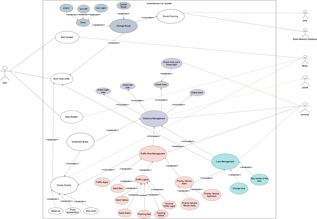
| Use Case Title | Description |
|---|---|
| Start System | User turns on the system. |
| Give Voice Order | User gives basic orders to system with voice. |
| Route Planning | System takes input location from user, verify its existence, finds shortest path to it. |
| Change Route | Changes the input location or cancels it. |
| Distance Management | Checks vehicles environment and finds estimate distance to objects. |
| Automatic Brake | Stops the car when an object appears in front of the car. |
| Lane Management | Manages the vehicle to stay center of the lane or change the lane base of the Priority Vehicle Alert or user’s request. |
| Cruise Control | Controls the acceleration. Slows down, speeds up or fixes acceleration of the vehicle. |
| Priority Vehicle Alert | Displays alert on the dash board and takes necessarily actions when an Emergency Vehicle approaches or moves away. |
| Solid Red | The traffic signal in front of the car has a solid red light. |
| Solid Yellow | The traffic signal in front of the car has a solid yellow light. |
| Solid Green | The traffic signal in front of the car has a solid green light. |
| Flashing Red | The traffic signal in front of the car has a flashing red light. |
| Flashing Yellow | The traffic signal in front of the car has a flashing yellow light. |
| Unusual Traffic Light | The traffic signal in front of the car not working correctly (no lights on, all lights on etc.). |
| Traffic Signs | When there is a Traffic Sign in front of the car. |
| Stop System | User turns off the system. |
3.2.1.1. Scenario: Start System
Description
User turns on the system to use the vehicle.
Functional Response
The systems will turn on the sensors and checks other components. Waits for destination input.
3.2.1.2. Scenario: Give Voice Order
Description
User can give orders by voice to change the destination or acceleration.
Functional Response
With the system’s virtual assistant system will get the order and based on it Cruise Control Module or Lane Management Module or Change Route Modules will be activated.
3.2.1.3. Scenario: Route Planning
Description
System takes destination input from user.
Functional Response
System gets destination input. If can’t find destination on GPS or road network database displays error message. If else, it calculates shortest path to destination and shows route.
3.2.1.4. Scenario: Change Route
Description
User can change route with voice order or can withdraw it.
Functional Response
Voice order will be recognized by system’s virtual assistant. Based on the user’s order new shortest path will be calculated or the vehicle will be parked on highway shoulder or parking areas until new order comes.
3.2.1.5. Scenario: Distance Management
Description
Checks vehicle’s environment and finds estimate distance to objects with the data comes from cameras and LIDAR.
Functional Response
The computer vision data is sent to the machine learning model for classification. The model classifies the selected area of the environment is clear or not. And tries to balance distance between objects and the vehicle.
3.2.1.6. Scenario: Automatic Brake
Description
Stops the car when an object appears in front of the car.
Functional Response
When an object suddenly appears in front of the car, system automatically stops the car. The car remains stationary so long as the obstacle is present. Once cleared, it continues its destination.
3.2.1.7. Scenario: Lane Management
Description
Manages the lane operations.
Functional Response
In the lane it’s balances the vehicle to stay in the center of the lane with the computer vision data comes from cameras. If there is a request from user to change the line uses Distance Management to check environment and changes the line based of the request.
3.2.1.8. Scenario: Cruise Control
Description
It controls the speed of the motor.
Functional Response
It changes the speed of the motor based on user’s order or responds comes from Distance Management module.
3.2.1.9. Scenario: Priority Vehicle Alert
Description
Displays alert on the dash board and takes necessarily actions when an Emergency Vehicle approaches or moves away.
Functional Response
When an emergency vehicle approaches, with audio sensors the vehicle will recognise sirens and with cameras and sensors it will check if emergency vehicle is behind of the car and not on the opposite side of the road, then will switch to an available line to clear emergency vehicle’s way. This module not only emptying based on one lane rule because emergency vehicle can approach from left lane, try to make an emergency corridor or can use shoulder of the road.
3.2.1.10. Scenario: Solid Red
Description
When there is a traffic light in front of the car with a solid red light. It means stop the car.
Functional Response
The car will slow down and stop until next signal input from computer vision.
3.2.1.11. Scenario: Solid Yellow
Description
When there is a traffic light in front of the car with a solid yellow light. It means get ready.
Functional Response
The car will slow down until the see next input. If it’s red Solid Red Use case will be on, if it’s green Solid Green Use case will be on.
3.2.1.12. Scenario: Solid Green
Description
When there is a traffic light in front of the car with a solid yellow light. It means go.
Functional Response
The car accelerates straight if there is no obstacle on the road.
3.2.1.13. Scenario: Flashing Red
Description
When there is a traffic light in front of the car with a flashing red light. It means the same as a stop sign. After stopping, proceed when safe and observe the right-of-way rules.
Functional Response
The car will slow down and stop until next signal input from computer vision.
3.2.1.14. Scenario: Flashing Yellow
Description
When there is a traffic light in front of the car with a flashing yellow light. It warns you to be careful. Slow down and be especially alert.
Functional Response
The vehicle will slow down and after checking environment with Distance Management. The car will continue its destination.
3.2.1.15. Scenario: Unusual Traffic Light
Description
When there is a traffic light in front of the car with no lights on or more than one lights on.
Functional Response
The vehicle will slow down and after checking environment with Distance Management. The car will continue its destination.
3.2.1.16. Scenario: Traffic Signs
Description
When there is a Traffic Sign in front of the car.
Functional Response
The computer vision data is sent to the machine learning model for classification. The model classifies the sign and acts based on it.
3.2.1.18. Scenario: Stop System
Description
Turns off the system.
Functional Response
When user wants to turn off the system, vehicle parks automatically in a safe area and stops the system.
3.3. Non-functional Requirements
This part includes non-functional requirements of the project.
3.3.1. Performance Requirements
| Performance Requirement | Description |
|---|---|
| Response Time | This system work in real-time. So, response time (T_response=T_actuation-T_event) must be 500 msecs. |
| Error Handling | When an unpredictable failure occurs, system need to recover briefly. |
| Workload | System should be able to handle many inputs from its environment in different challenging weather and traffic conditions. |
| Scalability | Sensors and other used hardware tools effective on it but we’re working on simulation there is no scalability requirement. |
3.3.2. Safety Requirements
| Safety Requirement | Description |
|---|---|
| Harm Protection | The autonomous car system needs to avoid accidents and shall not injure passengers. |
| Hazard Protection | The autonomous car system shall not start moving when its doors are still open. And notify user when safety belt has not worn. |
| Safety Error Identification | The vehicle needs to identify the system errors. |
| Safety Error Reporting | The system needs to notify user in the dangerous situation and let the user take vehicle’s control when system not working well. |
| Ethical Considerations | The system needs to take ethical decisions in case of emergency. |
| Detection and Response | The vehicle needs to follow the traffic rules, detects and responds to objects in its environment. |
3.3.3. Security Requirements
- The system needs to secure the sensors from external and internal threats.
- The algorithms behind these sensors must be secured.
3.3.4. Software Quality Attributes
| Quality Attribute | Description |
|---|---|
| Correctness | The system needs to recognize objects, follow the traffic rules and avoid accidents. |
| Reliability | Every functionality on the code must be able to work smoothly without failure under given normal conditions. |
| Learnability | The system needs to be simple enough to learn by users. |
| Robustness | The autonomous car must work properly under given abnormal traffic or weather conditions. |
| Maintainability | When an unpredictable failure occurs, system needs to correct defects their cause, repair it and report the failure. |
| Extensibility | Ability to extend the system is limitless. New functionalities can be added to system anytime. |
| Testability | Every functionality on the code must be able to work smoothly in simulation environment. |
| Efficiency | The system should work with maximum performance with minimum used energy and fuel. |
| Portability | The system should work on Linux and Windows. |
3.3.5. Business Rules
Our project uses Webots Self-Driving Vehicle Simulator. All the codes belong to us will be open source.
4. References
[1] https://en.wikipedia.org/wiki/Emergency_vehicle
[2] https://whatis.techtarget.com/definition/system-software
[3] https://en.wikipedia.org/wiki/Control_unit
